Turbocharger cut-out on a two-stroke engine, documented for EPA
Turbocharger cut-out on a two-stroke engine in service, measured onboard and documented for EPA.
Read the caseHome / Measurements
Standard emission measurements and methane slip, onboard or at your test bed, to IMO NTC 2008, ISO 8178 and EPA 40 CFR Part 1042 and 1065.
Measurements
Measured to NTC 2008 and ISO 8178, onboard or at your test bed.
Emission rules are getting stricter, and every certificate, amendment and emission report stands or falls on the measurement. We measure your engine’s current emission status with mobile equipment calibrated to NTC 2008, and deliver a report that documents the result the way class and the authorities expect.
NOx is the core of IMO engine certification. Our reports are used for Technical Files, amendments and Tier III SCR certification, and show what to adjust to meet the limits and run more efficiently, within regulation.
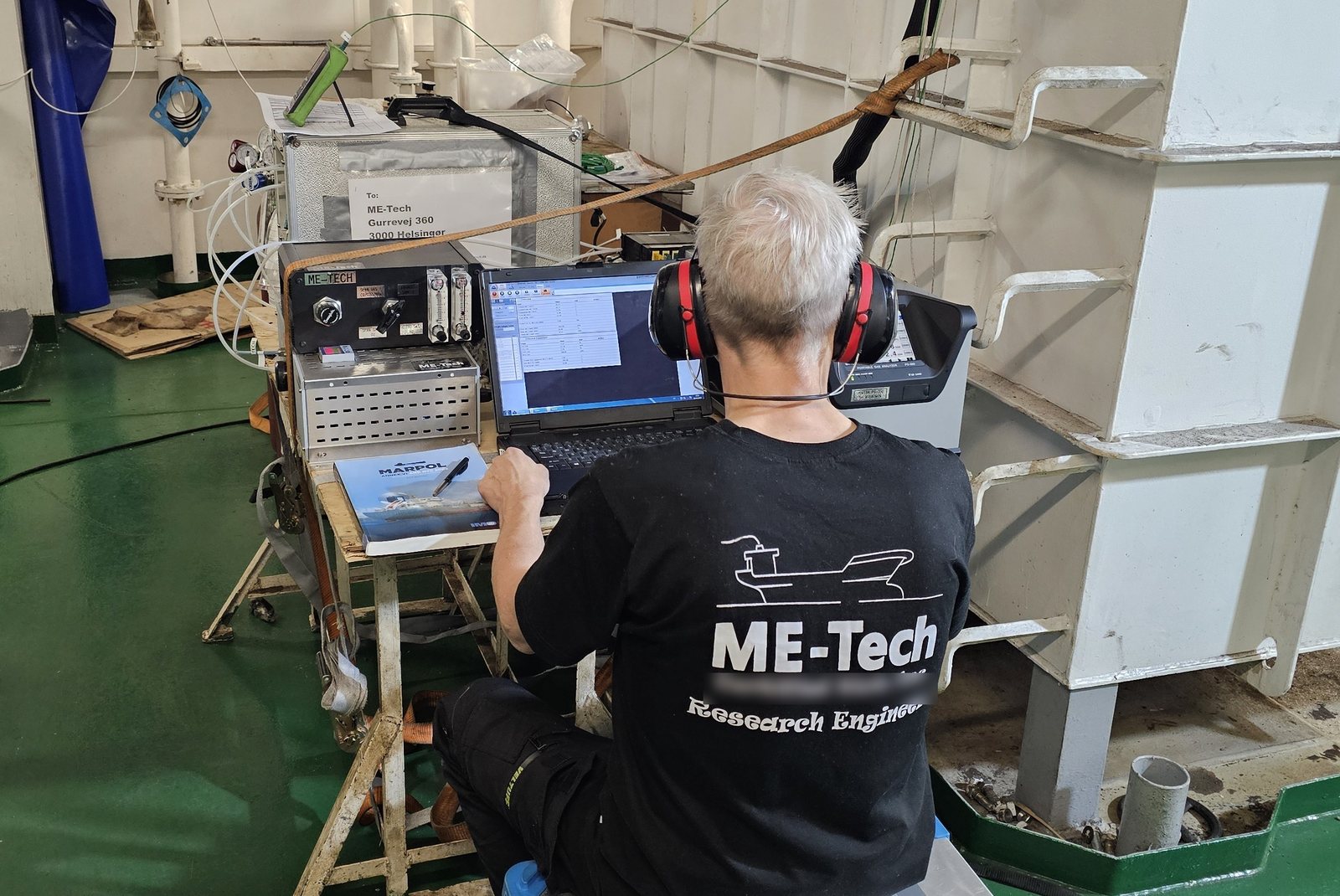 Onboard | Emission measurement
Default methane slip factors are conservative. A certified, measured value can replace the default under FuelEU Maritime, subject to the applicable certification, verification and requirements, and lower the reported GHG emissions of an LNG-fuelled vessel.
PM is measured gravimetrically: filters are weighed before and after by an accredited laboratory. We have done it at sea on a test programme approved by CARB.
Measuring at sea is demanding. Load, weather and fuel change, but the result must still stand up to survey. We bring a complete measurement rack, installed and operated by our technicians.
Measurements
Measured with the reference method in MEPC.414(84), documented as a basis for FuelEU.
Default methane slip factors are conservative, and may be far from what your engine actually emits.
A certified, measured value can replace the default under FuelEU Maritime, subject to the applicable certification, verification and requirements, and the effect on the reported GHG emissions can match other energy-saving measures.
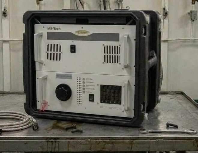 FTIR | Analyzer onboard
Measuring is also where reduction starts. Together with the engine designer, we use the measured data to see where the slip can be lowered by tuning, and we prove what a methane catalyst actually delivers.
We can measure with the reference method in MEPC.414(84): a heated FID with a non-methane cutter, with the methane response factor and cutter efficiencies documented. N2O, unburnt methanol and formaldehyde are measured by FTIR.
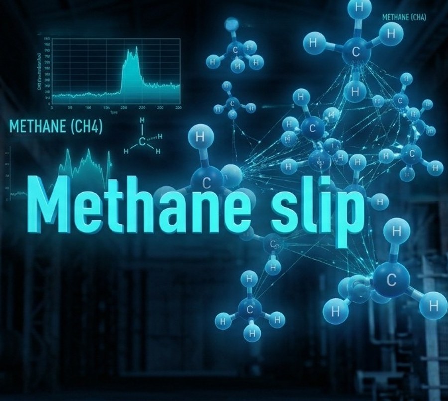 Methane slip | CH4 in the exhaust
We can measure at several load points, including the lowest gas mode point. Combined with the vessel’s logged load profile, the measured data gives a methane figure that reflects how the ship actually operates, not only the test bed cycle. You see the real emission, and can decide whether the measured value or the default factor serves you best, and whether the ship’s operating pattern supports the measured approach. Either way, a figure you can document and defend.
The measurement is only the start. Under MEPC.414(84) the results go into a CH4 and/or N2O file, which is submitted to the administration for verification. After approval, the administration issues a Statement of emission values. The same file, called the Methane File in the EU guidelines, is what FuelEU Maritime asks for when actual values are used. The next steps, such as Engine Load Monitoring and verification, are agreed with your verifier.
Measurements
Performance and emission tests for engine development.
Development work needs data you can trust, measured while the engine is being tuned.
We support engine designers, builders and research projects with performance and emission tests on two-stroke and four-stroke marine and stationary engines, at your test bed or onboard.
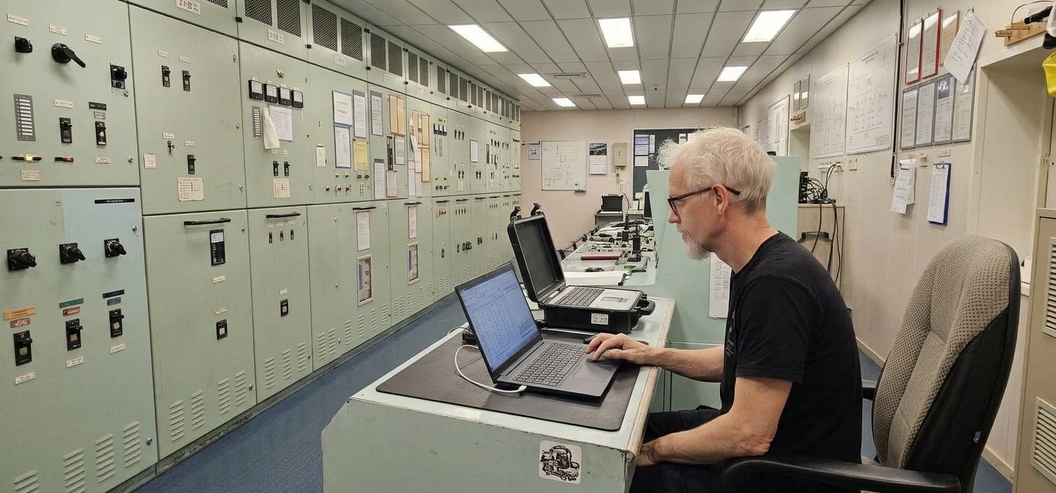 R&D | Data handling in the control room
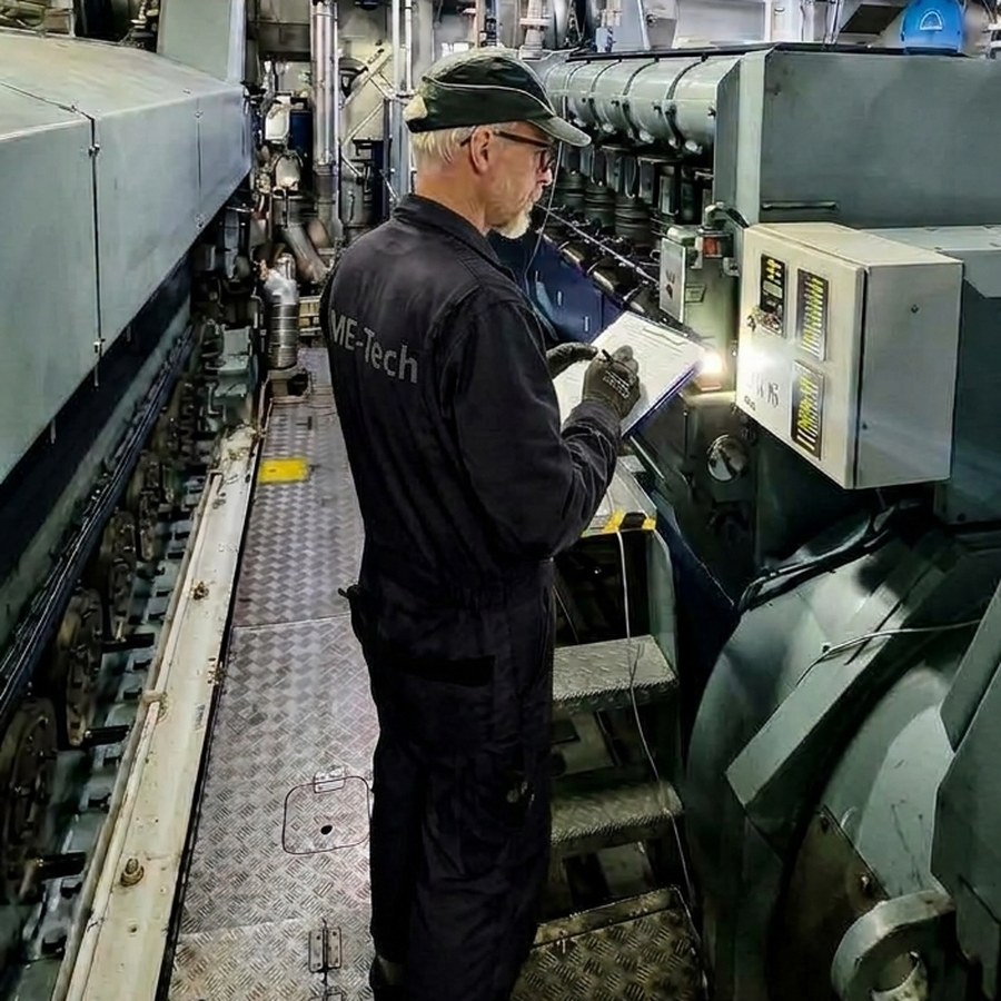 R&D | Reading the engine
Performance and emissions are measured together, so a change in settings, timing, turbocharging or fuel shows up in both. In close collaboration with your development engineers, the results are used straight away to take the next step.
We read engine data, such as cylinder pressure, together with the emission data.
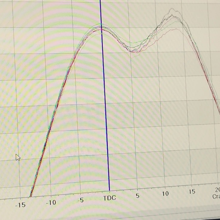 Engine cylinder pressure curve
Where a standard method does not fit the task, we help develop the measuring procedure and set up the equipment for it, so the development work is not held back by the measurement.
The results are documented so they can feed directly into the later certification, whether that is an amendment or a new Technical File.
Measurements
Gravimetric PM to ISO 8178 and EPA 40 CFR Part 1065, and smoke and black carbon by filter smoke number.
Particulate matter is weighed, smoke is measured by filter smoke number. Two methods, one measurement campaign, onboard or at your test bed.
PM is measured with the gravimetric method: a sample of the exhaust is diluted with clean air and drawn through filters, and the filters are weighed before and after by an accredited laboratory. Onboard or at your test bed.
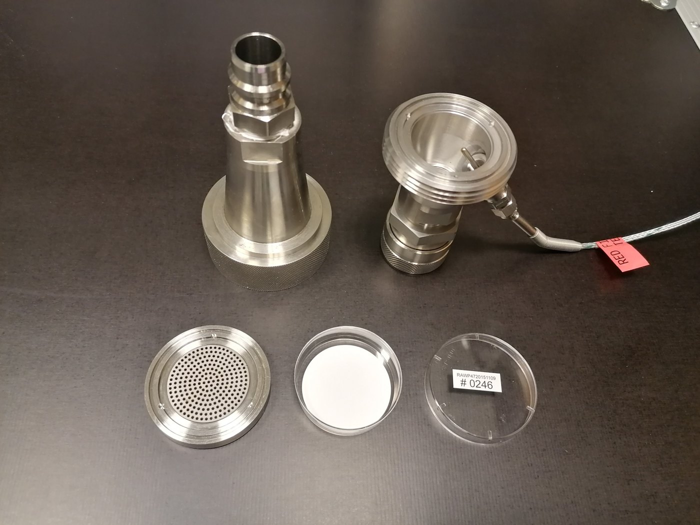 PM equipment | Filter holder, opened
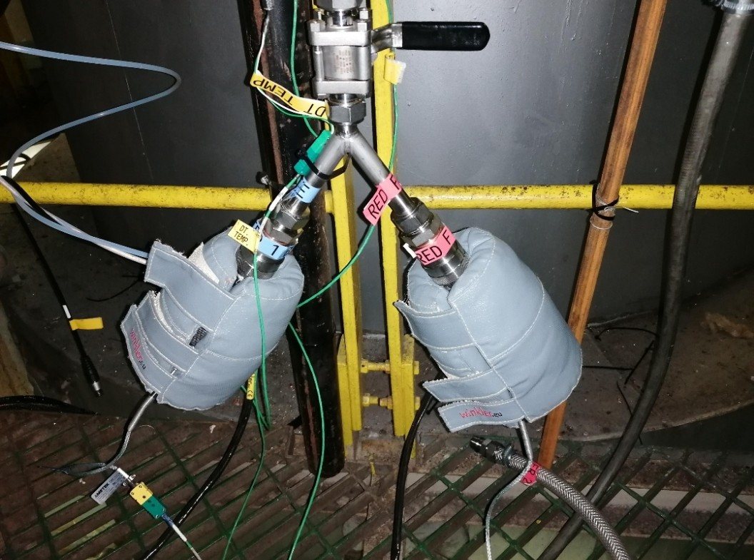 PM equipment | Two filter holders installed in parallel
The PM system is developed for the task and built to travel. It has been used on a test program approved by CARB, and the results are documented for the authorities.
An AVL smoke meter draws a sample of the exhaust through a filter paper. The blackening of the paper is read as the filter smoke number.
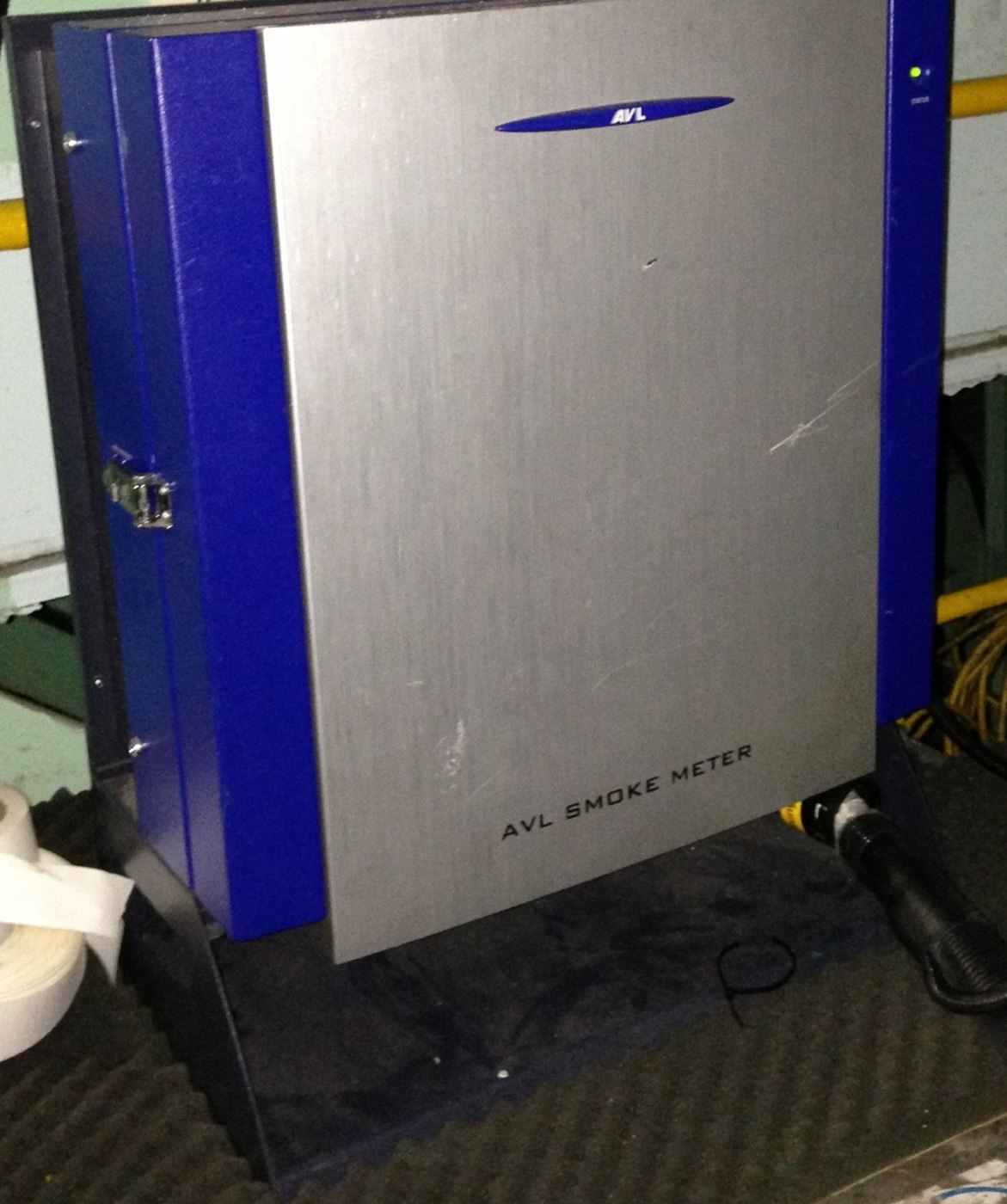 FSN | AVL smoke meter
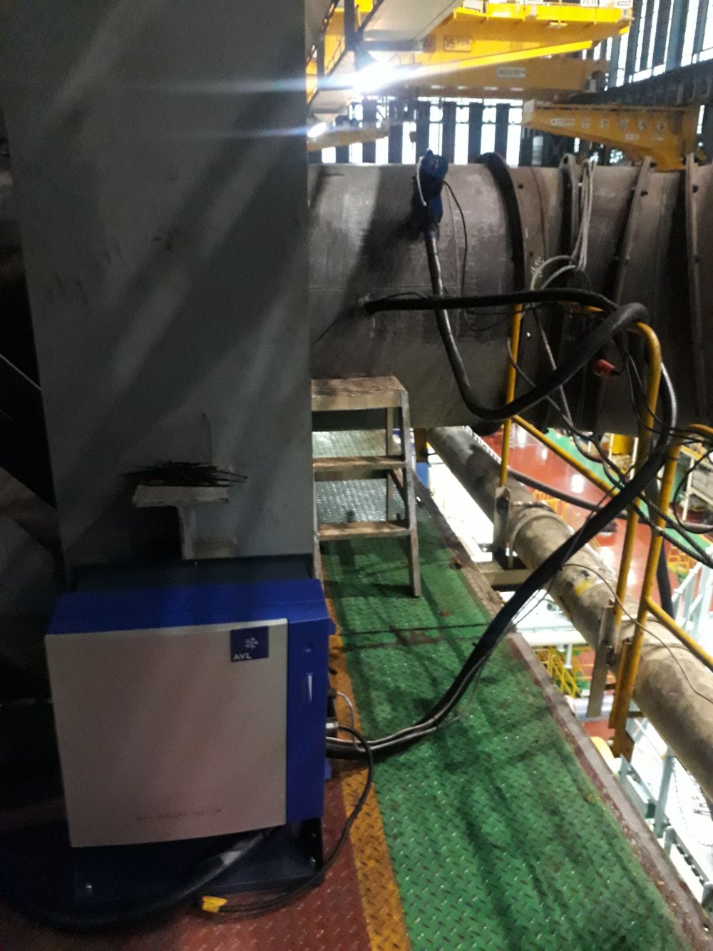 FSN | AVL smoke meter at the exhaust pipe
From the FSN, a black carbon concentration is derived. FSN is one of three methods recognised by IMO in the voluntary guidelines MEPC.394(82), which apply to ships operating in or near the Arctic.
Measurements
Keep your SCR approved, year after year.
Once a year we verify onboard that your SCR system still performs within its approved NOx limits, and give you a report that is ready for survey.
A true picture of the catalyst condition. The costly catalyst elements can stay in service as long as the measured NOx reduction allows, within the criteria of your Technical File, and are not replaced early because of a cautious manufacturer lifetime estimate or wrong analyzer data.
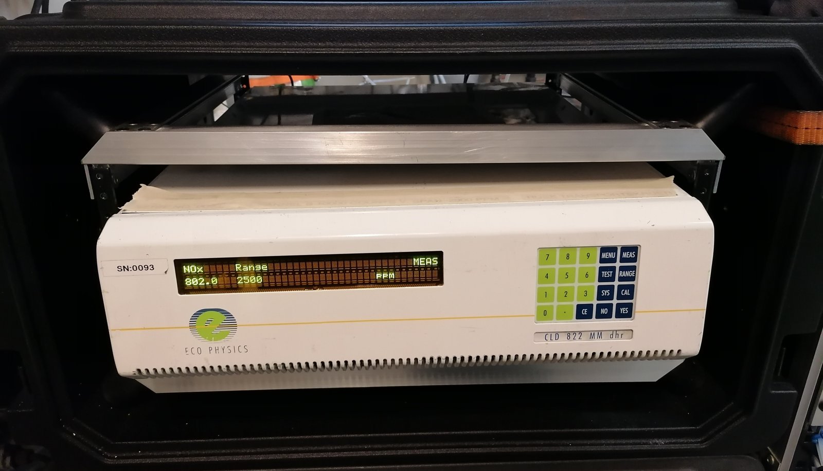 SCR spot check | NOx analyzer
The zero and span check is part of the spot check procedure. The analyzer must hold zero and span within the limits of the NOx Technical Code, so both gases are needed onboard for the test.
With an annual agreement, your SCR spot checks are scheduled in advance and carried out every year, so nothing is forgotten.
Measurements
Measurement work, shown in practice.
Turbocharger cut-out on a two-stroke engine in service, measured onboard and documented for EPA.
Read the caseNamed in the public report as responsible for the PM measurements, onboard a container ship.
Read the caseTell us the engine, the vessel and where it sails next.
